Application Note · AN-015 · Passive Components
Why Your 10 µF Capacitor Is Not 10 µF
Three Samsung capacitors. Same 10 µF, same X5R dielectric, same 25 V rating, same factory. At 12.5 V of DC bias the 1206 delivers 2.4× the capacitance of the 0603. Nothing on the label tells you this. One free graph does.
1. The board that met spec and still oscillated
Here is a failure mode we have seen more than once. You can reproduce it on paper in about a minute.
A board comes back marked “LDO unstable out of the box.” Same schematic as the reference design. Same regulator. Same 10 µF ceramic on the output. The only change is that somebody swapped the 1206 output capacitor for a 0603 to free up space near the connector.
The regulator’s datasheet asks for a minimum of 1 µF of effective output capacitance for stable operation. The BOM says 10 µF. That reads like a 10× safety factor, and nobody stops at a 10× safety factor in a design review.
You do not need a meter to find this fault. You need the manufacturer’s website. If the rail is 12 V, Samsung’s own DC bias curve for that 0603 shows it sitting near 1.9 µF — before you subtract its ±20% tolerance, before the cold end of the temperature range, before the few percent that Class II ceramics quietly shed with age. Stack those and the “10 µF” is hovering at, or below, the 1 µF the loop requires.
Nothing is broken. Nothing is counterfeit. The capacitor is doing exactly what its datasheet says it will do. The problem is that nobody read the one graph that mattered — and that graph is free, public, and ten minutes away.
Read a modern LDO datasheet carefully. Texas Instruments does not write “use a 1 µF output capacitor.” It writes that an effective output capacitance of a stated minimum is required for stability. On the TPS7A20 family that hard floor is 0.47 µF effective, with 1 µF the recommended design value. The word effective is the whole article. The silicon vendor already knows your capacitor is going to shrink. It is telling you to go and find out by how much.
2. Three capacitors, identical on paper
We pulled Samsung Electro-Mechanics’ published characteristic data for three parts. On paper they are the same capacitor:
| Parameter | CL10A106MA8NRN | CL21A106KAYNNN | CL31A106KAHNNN |
|---|---|---|---|
| Case size (imperial) | 0603 | 0805 | 1206 |
| Case size (metric) | 1608 | 2012 | 3216 |
| Body size | 1.6 × 0.8 mm | 2.0 × 1.25 mm | 3.2 × 1.6 mm |
| Thickness | 0.8 mm | 1.25 mm | 1.6 mm |
| Nominal capacitance | 10 µF | 10 µF | 10 µF |
| Dielectric | X5R | X5R | X5R |
| Rated voltage | 25 V | 25 V | 25 V |
| Tolerance | ±20% | ±10% | ±10% |
Same value. Same dielectric class. Same voltage rating. Same manufacturer, same process, same factory.
If you type 10uF 25V X5R into a BOM line, all three are legal answers. Any purchasing engineer optimising for cost and board area will hand you the 0603.
Now look at what they actually do.
3. What the DC bias curve actually shows
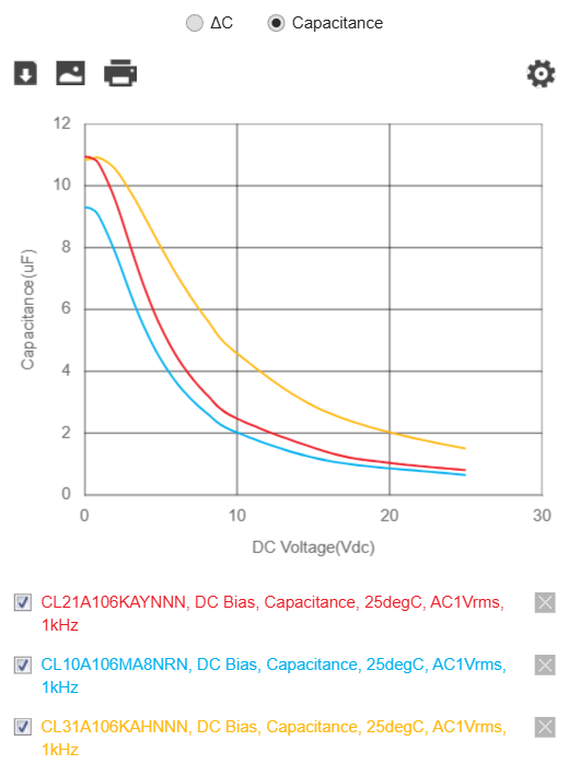
Every one of these parts starts near its rated value with no bias applied. Apply DC voltage — the thing a capacitor in a power circuit exists to have applied to it — and they separate immediately.
| DC bias | 0603 (CL10) | 0805 (CL21) | 1206 (CL31) |
|---|---|---|---|
| 0 V | 9.3 µF | 10.9 µF | 10.9 µF |
| 3.3 V | ≈ 7.3 µF | ≈ 8.6 µF | ≈ 9.9 µF |
| 5 V | ≈ 5.5 µF | ≈ 6.8 µF | ≈ 8.7 µF |
| 10 V | ≈ 1.9 µF | ≈ 2.4 µF | ≈ 4.7 µF |
| 12.5 V | ≈ 1.5 µF | ≈ 1.9 µF | ≈ 3.6 µF |
| 20 V | ≈ 0.85 µF | ≈ 1.05 µF | ≈ 2.0 µF |
| 25 V | ≈ 0.65 µF | ≈ 0.80 µF | ≈ 1.5 µF |
Read the 5 V row again. That is a USB rail. That is the input of half the modules on your desk. The 1206 keeps 80% of its capacitance. The 0603 keeps 59%.
Now read the 12.5 V row — half the rated voltage, which most engineers would call a comfortable design point. The 1206 keeps about a third. The 0603 keeps about a sixth. The 1206 delivers 2.4× the capacitance of the 0603, from the same 10 µF printed on the reel.
Put differently: to build a genuine 10 µF at 12.5 V, you need three 1206s — or seven 0603s. That is the real exchange rate, and it is nowhere on the label.
4. Why case size changes anything at all
This surprises people because the mechanism is invisible. Here it is.
X5R and X7R are Class II ceramics. The dielectric is barium titanate, a ferroelectric material. Its enormous permittivity comes from electric domains inside the ceramic that are free to reorient when you wiggle the field. That freedom is where the capacitance comes from.
Apply a DC field and those domains get pinned. They stop reorienting. Permittivity collapses — and with it, capacitance.
The critical detail: the domains respond to electric field strength, not to voltage. And field strength is voltage divided by the thickness of one dielectric layer:
An MLCC is a stack. Its capacitance is:
where A is the overlap area of one electrode pair and N is the number of layers.
Now the trade-off writes itself. To force 10 µF into a 0603 body you have almost no A and limited room for N, so you must make d_layer as thin as physically possible — sub-micron, in modern parts. Thin layers mean a brutal E-field for any applied voltage. Domains pin early. Capacitance falls off a cliff.
A 1206 has four times the footprint area and twice the thickness of a 0603. It reaches the same 10 µF with a much thicker dielectric layer and a larger electrode area. At 12.5 V its internal field is a fraction of the 0603’s. Its domains are still moving. Its capacitance is still there.
Case size is a proxy. The real variable is capacitance density.
This distinction matters, and almost nobody states it out loud.
The ceramic does not know what case size it lives in. It only knows the field across it, and the field is set by d_layer. Case size matters only because it constrains how thin the layers have to be. What actually determines d_layer is how much capacitance you demanded from the available volume.
So the same 0603 that collapses to 16% of nameplate at 10 µF behaves far better at 2.2 µF, and behaves almost like a Class I part at 100 nF. Nothing about the package changed. The designer simply stopped asking the ceramic for the impossible, so the manufacturer could use thicker layers and fewer of them.
Two practical consequences follow, and they point in opposite directions:
- A small capacitor is not automatically a bad capacitor. A 100 nF 0402 decoupling cap on a 3.3 V rail loses very little. Do not go fitting 1206s all over your digital section because of this article.
- A large capacitance is what forces you into a large case. When you genuinely need 10 µF of effective capacitance under bias — bulk storage, LDO stability, converter output — the volume is not optional. Physics is charging you for the microfarads, not for the footprint.
Which is exactly the situation on both of our modules. We are not using a 1206 because bigger is better. We are using it because we need a real 10 µF at 5 V, and there is no honest way to buy that in a 0603.
Bigger case size does not “add margin.” It lowers the electric field inside the ceramic for the same applied voltage — by letting the manufacturer use thicker dielectric layers to reach the value you asked for. Case size is the lever you control. Field strength is what the ceramic responds to. Everything else in this note follows from that.
5. Rated voltage is a survival spec, not a capacitance spec
This is the misunderstanding I see most often, including from experienced engineers.
All three parts above are rated 25 V. All three will happily sit at 25 V for years without breaking down. The rating tells you the part survives. It says nothing whatsoever about how much capacitance is left when it gets there.
At 25 V, the 25 V-rated 0603 has 0.65 µF. It is a fully compliant, in-specification, correctly rated capacitor delivering 6.5% of its marked value.
Raising the voltage rating helps — a 50 V part has thicker layers than a 25 V part of the same size and value — but it is a weaker lever than case size, and above some point the part simply cannot be built. Case size is the lever that actually moves.
6. Temperature, bias, and the tolerance you were taught
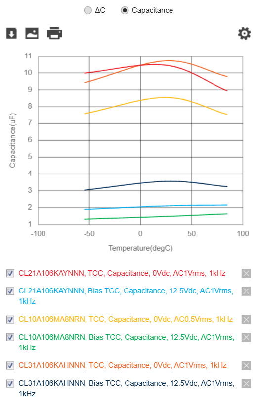
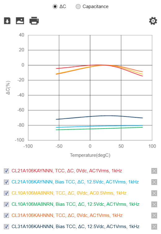
With no bias, all three parts behave like textbook X5R: a gentle hump, staying inside roughly ±15% from −55 °C to +85 °C. Everyone knows this graph. Everyone is comfortable with it.
Now switch the bias on. The three lower curves drop to a completely different world:
| At 12.5 V bias | ΔC at −55 °C | ΔC at +25 °C | ΔC at +85 °C |
|---|---|---|---|
| 1206 | ≈ −72% | ≈ −68% | ≈ −70% |
| 0805 | ≈ −85% | ≈ −80% | ≈ −80% |
| 0603 | ≈ −86% | ≈ −83% | ≈ −82% |
Two things worth noticing.
First, the biased curves are flat. Once the domains are pinned, temperature has little left to modulate. You have traded a well-behaved ±15% part for a badly-behaved but stable −80% part. That is not a comfort.
Second, and this is the part that gets designs into trouble: the ±15% X5R tolerance you were taught to design against is measured at zero bias. It is not your operating condition. It was never your operating condition.
One more effect that appears on no graph here: Class II ceramics age. Barium titanate slowly loses permittivity after the thermal shock of reflow — typically a few percent per decade of hours. A capacitor measured on day one is not the capacitor running in the field two years later. Reputable manufacturers publish the aging rate. Everyone else lets you find out.
7. The AC drive level nobody mentions
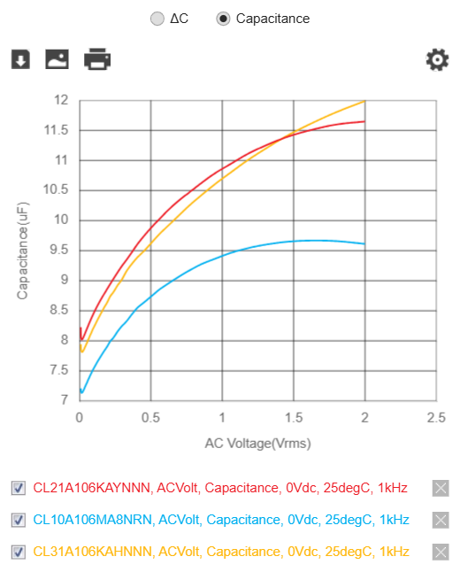
Here is a subtlety that separates careful engineers from confident ones. Class II capacitance also depends on how hard you measure it.
At 0.1 Vrms of AC drive the 1206 measures around 8 µF. At 1.0 Vrms the same part measures 10.9 µF. Same capacitor, same instrument, same afternoon.
This is why datasheet conditions are always stated as 1 kHz, 1 Vrms, 0 Vdc. It is also why a perfectly good handheld LCR meter — most of which drive somewhere around 0.3–0.5 Vrms — will read your 10 µF capacitor as 8-point-something, and you will spend an evening wondering whether you bought fakes. You did not. Your meter simply asked the capacitor a gentler question than the datasheet did.
Look closely at Samsung’s own legend in Figures 2 and 3: the 0603 was characterised at AC 0.5 Vrms, not 1 Vrms, which is why its zero-bias line sits lower than its siblings. Datasheet fine print is not decoration.
A benchtop or handheld LCR meter measures capacitance with zero DC bias applied. It cannot show you derating, because it cannot create the condition that causes derating. Reading 9.8 µF on a 10 µF part proves the part is real. It proves nothing about what that part will be worth on your 12 V rail. To measure derating you need a DC bias fixture that superimposes DC across the part while blocking it from the meter’s front end. Most engineers do not have one. All engineers have access to the vendor’s curve.
8. Where the 1206 actually loses
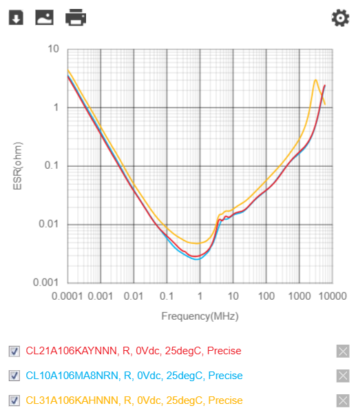
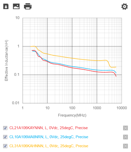
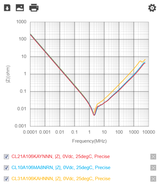
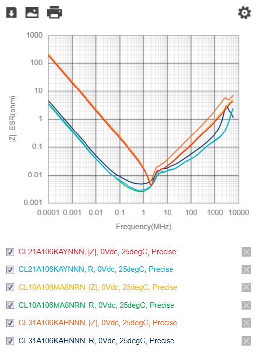
I would be a poor engineer and a worse salesman if I told you bigger is always better. It is not. Samsung’s data shows exactly where the 1206 gives something back.
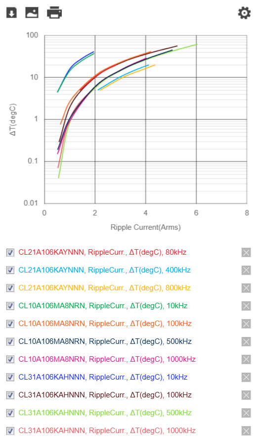
There is one more honest caution. A 1206 spans more board and is stiffer relative to the FR4 under it, so it is measurably more susceptible to flex cracking near depanel routes, mounting screws and connector edges. If you place 1206 bulk capacitors, keep them away from board edges and mouse-bites, orient the long axis parallel to the expected bend axis, and consider soft-termination parts.
So the honest rule is: 1206 for bulk energy storage under DC bias. 0402/0603 for high-frequency decoupling where there is little or no bias and inductance is king. They are different jobs. Use both.
Key takeaways
- A 10 µF X5R capacitor is 10 µF only at zero volts. Under bias it can lose 60–90% of its value.
- Derating is driven by electric field inside the ceramic,
E = V / d_layer. A larger case reaches the same capacitance with thicker layers, so its field — and its loss — is smaller. - Case size is a proxy. The real variable is capacitance density. A 100 nF 0402 barely derates; a 10 µF 0603 falls off a cliff. Same package family, different demand on the ceramic.
- At 12.5 V, a 1206 delivers 2.4× the capacitance of a 0603 with the identical marking.
- Rated voltage is a survival spec. A 25 V 0603 at 25 V is in spec and delivering 6.5% of nameplate.
- The ±15% X5R tolerance is measured at zero bias. It is not your operating condition.
- Your LCR meter cannot show you derating, because it applies no DC bias. Only the vendor’s curve can.
- Bigger is not universally better: the 1206 loses on ESR, ESL, high-frequency impedance and flex-crack resistance. It wins decisively on biased capacitance and ripple current.
9. Why our modules use a 1206
We use Samsung CL31A106KAHNNNE — 10 µF, X5R, 25 V, 1206 — on both the TrueVolt LN-7A2033 and the PureRail C33 Nano. Both run from a 5 V class rail. Someone will eventually ask why we “wasted” a 25 V part and a 1206 footprint on a 5 V module.
We did not choose 25 V for breakdown margin. We chose it for capacitance margin. At 5 V bias that 1206 still delivers about 8.7 µF. A 10 µF 0603 rated 6.3 V — the part most cost-optimised boards use in that slot — would be sitting somewhere near 2 µF at the same 5 V.
TrueVolt LN-7A2033
For the TrueVolt LN-7A2033, the output capacitor is not decoration. Texas Instruments specifies an effective output capacitance range for the TPS7A2033 — a minimum of 0.47 µF and a maximum of 200 µF — for stable operation, and designs its application examples around 1 µF. The noise and PSRR figures in that datasheet are quoted with a specific output capacitor in place.
Our headline numbers — 7 µVrms output noise (10 Hz–100 kHz) and 95 dB PSRR at 1 kHz — are TI’s datasheet figures for this regulator under its stated conditions. They are the reason we chose it. They are also conditional: they assume the capacitor on the board still is the capacitor the datasheet assumed.
To be plain about it: a 7 µVrms noise floor is not something you confirm with an oscilloscope. A good DSO’s own input noise sits one to two orders of magnitude above that. Numbers at that level need a low-noise preamplifier ahead of a spectrum analyser, or an FFT with a calibrated and characterised noise floor. What we can control, and do, is the condition the datasheet assumes. Fit a part whose effective capacitance at bias is a quarter of its marking and you are no longer running the regulator TI characterised. You are running a different regulator that happens to share a part number.
PureRail C33 Nano
For the PureRail C33 Nano, the same capacitor sits on the USB-C input. It absorbs the ringing from cable inductance at hot-plug and feeds the LDO during load steps. A collapsed input capacitor here shows up as input droop during transients, which the LDO then obediently passes through to your ADC reference.
This is why our BOM says CL31A106KAHNNNE and not 10uF 25V X5R. Those are not the same instruction.
10. Why we buy Samsung — and why it is not about nationality
Let me be precise, because this argument is often made badly.
There are good MLCC manufacturers outside the big Japanese and Korean names. Yageo, Walsin, Fenghua and Samwha make real parts, and several of them publish real data. The problem is not a country. The problem is the anonymous reel.
MLCCs are unmarked. There is no printing on the body. A 10 µF 1206 X5R 25 V and a 10 µF 1206 Y5V 16 V are visually indistinguishable — and Y5V loses over 80% of its capacitance across its temperature range before you apply any bias at all.
When you buy from Samsung, Murata, TDK or Kyocera-AVX through an authorised distributor, you get:
| What you receive | Why it matters |
|---|---|
| DC bias curve for that exact part number | Tells you your real capacitance. Nothing else does. |
| Bias-and-temperature characteristics together | Worst case is cold and biased, not one at a time. |
| ESR, |Z| and ESL vs frequency | Lets you predict decoupling and loop behaviour. |
| Ripple current vs ΔT at several frequencies | Sets your thermal and lifetime budget. |
| S-parameter and SPICE models | Lets you simulate before you spin a board. |
| Published aging rate | Tells you what the part is worth in year three. |
| Date code and lot code traceability | The part you qualify in July is the part you receive in March. |
When you buy the unbranded reel from a marketplace, you get one line: 10 µF, 25 V, X5R, ±10%. No curve. No model. No lot traceability. No guarantee that the next reel came off the same process.
Without a DC bias curve, you cannot simulate your power supply and you cannot know your loop. You are not being frugal. You are designing blind and calling the result “it worked on my bench.” Every graph in this note came free from Samsung Electro-Mechanics’ online MLCC characteristics viewer, in about ten minutes. That data is the product. The ceramic is almost incidental.
11. Design checklist
| Step | What to do |
|---|---|
| 1 | Never design against the printed value. Design against capacitance at your worst-case DC bias, worst-case temperature and real AC drive. |
| 2 | Pull the vendor’s DC bias curve before you commit the footprint. If the vendor cannot give you one, you have chosen the wrong vendor — not the wrong capacitor. |
| 3 | Write the effective value into the schematic note: C3 = 10µF nom / 8.7µF @ 5V. Your future self will thank you at 2 a.m. |
| 4 | Split the job. Bulk energy under bias → larger case, higher voltage rating. High-frequency decoupling → smallest case, lowest ESL. |
| 5 | Check the silicon vendor’s wording. If the datasheet says effective capacitance, it has already told you to derate. |
| 6 | If DC bias derating is unacceptable, leave Class II. C0G/NP0 has essentially zero voltage coefficient — and is physically enormous at 10 µF. Film and polymer tantalum are the other exits. |
| 7 | When you shrink a footprint, re-check the capacitor. Case-size reduction is a capacitance change, not a mechanical one. |
| 8 | Keep 1206 bulk capacitors away from board edges, mouse-bites and mounting holes to avoid flex cracks. |
12. Frequently asked questions
Does a 10 µF 0603 capacitor really lose 80% of its capacitance?
Yes, if it is a Class II (X5R/X7R) part operating near half its rated voltage. Samsung’s own curve for the 25 V CL10A106MA8NRN shows roughly 1.5 µF remaining at 12.5 V DC — about 16% of its zero-bias value. This is normal, in-specification behaviour, not a defect and not a counterfeit part.
Will a higher voltage rating fix DC bias derating?
Partly. A 50 V part uses thicker dielectric layers than a 25 V part of the same case and value, so it derates less. But case size is the stronger lever, because it buys both thicker layers and more electrode area at once.
Is X7R better than X5R for DC bias?
Not inherently. X7R and X5R differ in their temperature stability range, not their voltage coefficient. Both are barium-titanate Class II ceramics and both derate heavily with bias. Only Class I (C0G/NP0) is effectively immune.
Can I parallel several 0603 capacitors instead of using one 1206?
You can, and sometimes you should — an array of small capacitors has lower total ESL. But at 12.5 V you need about seven 0603s to equal three 1206s: seven placements, fourteen pads, seven more chances of a solder defect. What people actually do is fit one 0603 and never find out.
Why does Ramanu Systems use a 25 V 1206 capacitor on a 5 V module?
For capacitance, not for breakdown. At 5 V bias the 25 V 1206 still delivers about 8.7 µF of its 10.9 µF zero-bias value. A 6.3 V 0603 in the same slot would deliver roughly 2 µF. The regulator’s datasheet stability and PSRR conditions assume a real capacitance, not a printed one. We would rather ship the condition than the label.
Can I measure DC bias derating with my LCR meter?
Not with the meter alone. A standard LCR meter applies no DC bias, so it measures the zero-bias value no matter what your circuit does. You need a DC bias fixture that superimposes DC across the part while protecting the meter’s front end. Without one, use the manufacturer’s published curve.
Where do I get the DC bias curve for my capacitor?
Samsung Electro-Mechanics, Murata (SimSurfing), TDK and Kyocera-AVX all publish free online characteristic viewers with per-part-number data. If your capacitor’s manufacturer does not, treat that absence as the specification it is.
Does a 2.2 µF 0603 derate as badly as a 10 µF 0603?
No. Derating tracks capacitance density, not case size directly. A 0603 holding 2.2 µF can use thicker dielectric layers than one squeezing in 10 µF, so its internal field at a given voltage is lower and it keeps considerably more of its value. A 100 nF 0402 on a 3.3 V rail loses very little. The lesson of this article is not “always use 1206” — it is “check the curve for the exact value, case and rating you are buying.”
Which capacitors did this article compare?
Three Samsung Electro-Mechanics parts, all 10 µF, X5R, 25 V: CL10A106MA8NRN (0603), CL21A106KAYNNN (0805) and CL31A106KAHNNN (1206). Search those part numbers in Samsung’s characteristics viewer and you can regenerate every graph above yourself in about ten minutes.
Modules built on parts we can prove
Ramanu Systems designs precision power modules in Pune using genuine Tier-1 components from authorised distributors — because a capacitor without a published DC bias curve is not a specification, it is a guess. Both modules below carry the Samsung CL31A106KAHNNNE discussed in this note.