Aluminum PCB vs FR4:
The Thermal Response Gap Is Real.
We placed two identical temperature sensor modules — one on aluminum MCPCB, one on standard FR4 — on the same hot plate at the same time. The aluminum module reached 88°C while the FR4 module was still at 65°C. Here is the data.
Key Findings — Aluminum PCB vs FR4 Thermal Response
- Aluminum MCPCB responds approximately 2× faster than standard FR4 PCB when both are placed on the same heated surface simultaneously.
- At 35 seconds: Aluminum PCB sensor reads 88°C while FR4 PCB sensor reads only 65°C — a 23°C measurement gap from the same heat source.
- At 5 seconds: Aluminum has already reached ~50°C while FR4 is still at ~35°C — the gap opens immediately and widens throughout the test.
- Thermal conductivity explains the gap: Aluminum MCPCB conducts heat at 1.0–3.0 W/m·K vs FR4’s ~0.25 W/m·K — an 8–12× difference in thermal conductivity.
- For thermal protection applications (3D printers, motors, battery packs), this speed difference is the margin between catching a thermal runaway and missing it.
- No thermal grease was used in this test — both modules were simply pressed onto the hot plate by hand, representing worst-case real-world mounting conditions.
- This experiment was conducted using the Ramanu Systems SwiftSense T235 module with genuine TI TMP235 analog temperature sensor on aluminum MCPCB.
Why PCB Material Matters for Temperature Sensing
A temperature sensor IC can only measure what it physically feels. If the PCB substrate between the sensor and the heat source acts as a thermal insulator, the sensor reads a delayed, attenuated version of reality — not the actual surface temperature.
Standard FR4 fiberglass-epoxy is an excellent electrical insulator — and unfortunately, an equally excellent thermal insulator. With a thermal conductivity of just ~0.25 W/m·K, FR4 creates a bottleneck between the heat source and the sensor die. The sensor thinks the surface is cooler than it actually is, and it responds slower than the thermal event actually occurs.
Aluminum MCPCB (Metal Core PCB) solves this by replacing the FR4 core with an aluminum substrate that conducts heat 8–12× faster. The sensor die tracks the surface temperature almost immediately, giving you the thermal response speed that protection circuits demand.
Experiment Setup
We designed this experiment to answer one question: how much faster does an aluminum PCB temperature sensor respond compared to an identical sensor on FR4?
Methodology
| Parameter | Detail |
|---|---|
| Sensor IC | TI TMP235 analog temperature sensor (identical on both modules) |
| Module A | SwiftSense T235 on aluminum MCPCB (1.0–3.0 W/m·K) |
| Module B | Same TMP235 circuit on standard FR4 PCB (~0.25 W/m·K) |
| Heat Source | Constant-temperature hot plate |
| Mounting | Both modules pressed simultaneously by hand onto the hot plate |
| Thermal Interface | None — no thermal grease or pad used (worst-case condition) |
| Data Capture | ADC readings at ~1 second intervals, converted to temperature via LUT |
| Duration | 35 seconds from room temperature (~32°C) |
| Data Processing | Moving average filter applied to reduce ADC noise |
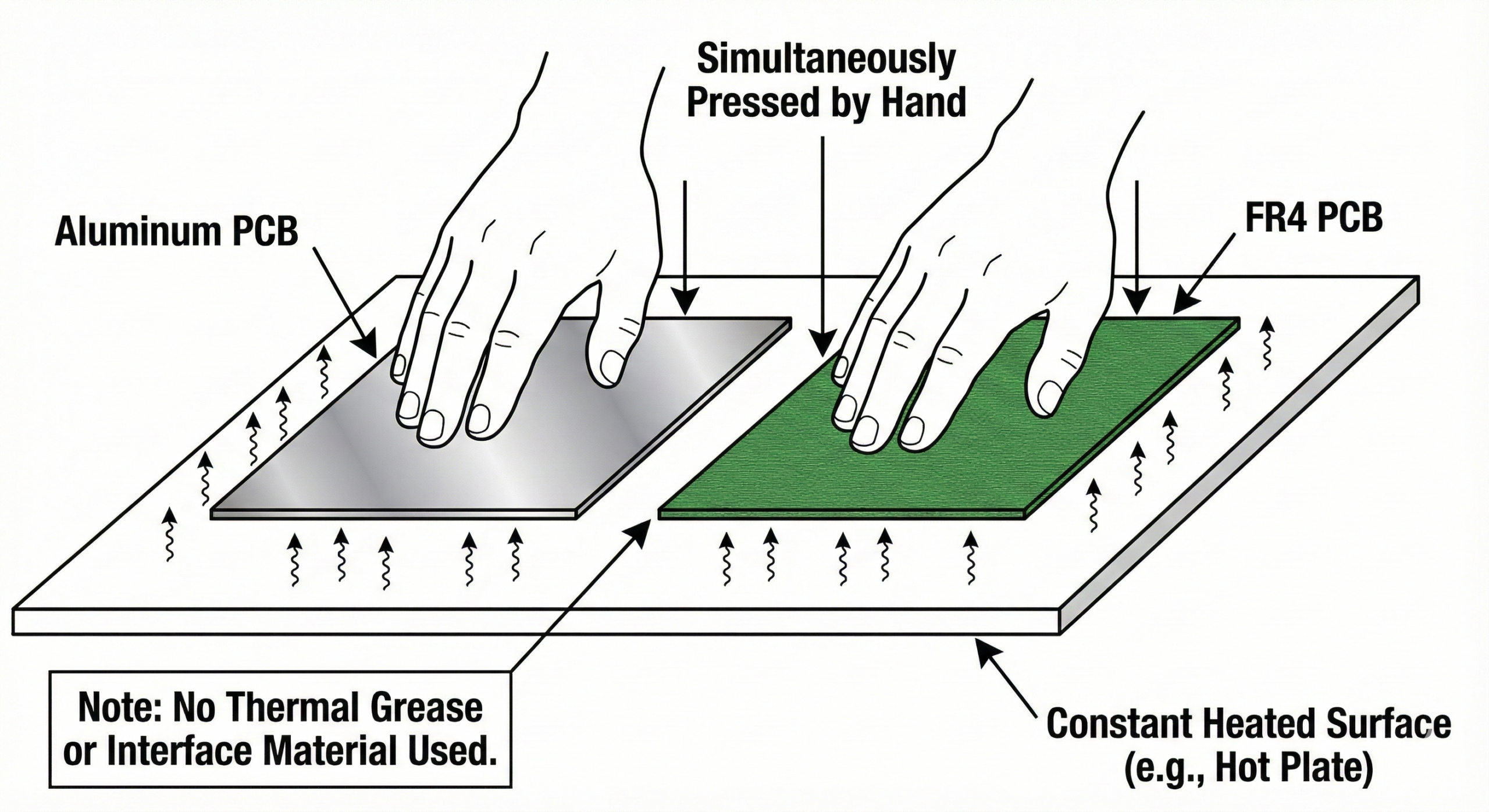
The key design choice was no thermal interface material. In real-world applications — especially 3D printers, motor casings, and field deployments — sensors are often mounted with imperfect thermal contact. This test represents the realistic worst case, not an idealized laboratory condition.
Results: The Thermal Response Curve
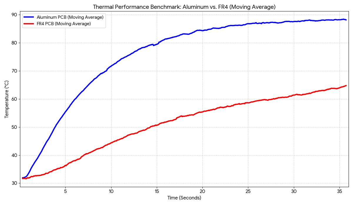
The data tells a clear story. Both modules start at room temperature (~32°C). Within the first 5 seconds, the aluminum module has already reached ~50°C while the FR4 module is still at ~35°C. The gap opens immediately and continues to widen.
Key Data Points
| Time | Aluminum PCB | FR4 PCB | Gap |
|---|---|---|---|
| 0 seconds | 32°C | 32°C | 0°C |
| 5 seconds | ~50°C | ~35°C | ~15°C |
| 10 seconds | ~70°C | ~44°C | ~26°C |
| 15 seconds | ~79°C | ~50°C | ~29°C |
| 20 seconds | ~84°C | ~55°C | ~29°C |
| 25 seconds | ~86°C | ~58°C | ~28°C |
| 35 seconds | ~88°C | ~65°C | ~23°C |
What the Data Means for Your Design
The FR4 Module Isn’t Wrong — It’s Late
Both sensors are measuring accurately for their respective thermal environments. The FR4 sensor correctly reports the temperature of the FR4 substrate’s top surface. But that surface is 23°C cooler than the actual heat source because FR4 is blocking the heat transfer. The aluminum module reports a temperature much closer to the actual source because aluminum conducts heat through to the sensor almost immediately.
Speed Matters More Than Accuracy
A sensor with ±0.5°C accuracy on FR4 that reads 65°C when the surface is actually 88°C is not delivering “±0.5°C accuracy” in any meaningful sense. The accuracy specification applies to the sensor IC itself — but the PCB material determines whether that accuracy has access to the real temperature. Aluminum MCPCB closes the gap between sensor accuracy and system accuracy.
The Self-Heating Advantage
Every temperature sensor dissipates a small amount of power through its bias current, causing self-heating error. On FR4, that heat is trapped near the sensor die because FR4 is a thermal insulator — inflating the reading. On aluminum MCPCB, the self-heating energy is immediately conducted away into the substrate. The SwiftSense T235’s ultra-low power consumption (~35µA supply current) further minimizes self-heating error on the aluminum substrate.
Material Property Comparison
| Property | FR4 (Fiberglass-Epoxy) | Aluminum MCPCB | Winner |
|---|---|---|---|
| Thermal Conductivity | ~0.25 W/m·K | 1.0–3.0 W/m·K | Aluminum 8–12× |
| Thermal Response | Slow — insulates sensor from source | Fast — conducts heat to sensor immediately | Aluminum |
| Self-Heating Dissipation | Traps heat near sensor die | Conducts self-heating away | Aluminum |
| Max Operating Temp | ~130°C (laminate degrades) | 150°C+ (aluminum substrate) | Aluminum |
| Mechanical Rigidity | Can flex and delaminate | Rigid aluminum core | Aluminum |
| Cost | Lower | Higher | FR4 |
Where Aluminum PCB Matters Most
Looking at heat dissipation rather than sensing speed? See our companion test: Aluminum PCB vs FR4 thermal test on a 3.3V LDO regulator (with video).
Not every application needs aluminum MCPCB. If you’re measuring room temperature for a weather station, FR4 is fine — the temperature changes slowly over minutes. But in these applications, the 2× faster response of aluminum is critical:
3D Printer Hot-End and Heated Bed Protection
Thermal runaway in a 3D printer can start a fire in under 30 seconds. An FR4-based sensor that lags 15 seconds behind the actual temperature gives your firmware half the time to react. Aluminum MCPCB gives your thermal protection algorithm the fastest possible view of the actual hot-end temperature.
Motor and Transformer Temperature Monitoring
A locked rotor condition can overheat a motor winding in seconds. The sensor must track the winding temperature as fast as the thermal event progresses. Aluminum MCPCB mounted with thermal paste on the motor casing provides near-real-time temperature tracking.
Battery Pack Thermal Management
Lithium cells can enter thermal runaway if internal temperature exceeds safe limits. Aluminum MCPCB sensors mounted on cell tabs or bus bars give the BMS (Battery Management System) the earliest possible warning of a thermal event.
Industrial Process Control
In closed-loop thermal control systems, sensor lag causes overshoot. A sensor on aluminum MCPCB reduces the effective lag in the control loop, improving temperature regulation accuracy and reducing thermal cycling stress on the controlled equipment.
Get the Sensor That Responds in Time
Aluminum MCPCB. Genuine TI TMP235. ±0.5°C accuracy. 10mV/°C linear output. Made in India.