Fundamentals · ADC · Arduino · ESP32 · ADS1115 · HX711 · ADS1256
ADC Resolution vs Accuracy: Why More Bits Won’t Fix Noisy Readings
ADC resolution vs accuracy: you upgraded from 10-bit to 24-bit, and now
More bits don’t buy accuracy. Higher resolution comes with higher responsibility.
Ramanu Systems · Pune, India · 4-minute answer, 15-minute deep dive
Resolution is how many steps the ADC divides its reference into. Accuracy is how close, and how steady, the reading is to the truth. Every extra bit halves the step size, so it also halves the noise you can afford.
In most circuits the ADC’s reference is the analog supply, so supply noise goes straight into every reading. And the ADC’s ability to reject supply noise (PSRR) is limited and falls as frequency rises. Fix the supply and reference first, then buy bits.
Resolution vs accuracy, in one picture
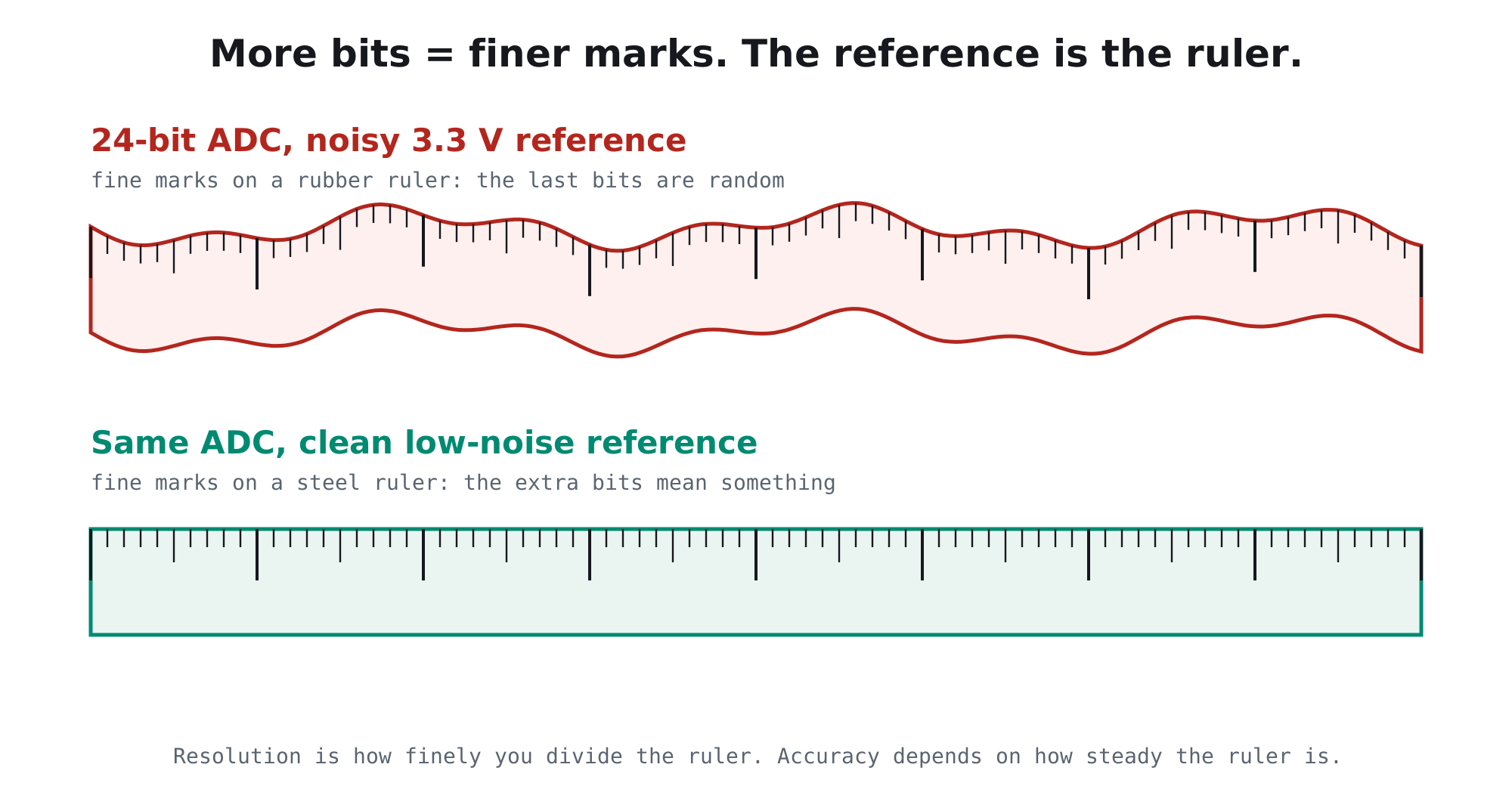
Think of the ADC reference as a ruler. Resolution is how finely the ruler is marked. A 24-bit ADC has very fine marks. But if the ruler itself stretches and shrinks with every bit of supply noise, those fine marks just measure the wobble.
How small is one step?
Here is one step (LSB) on a 3.3 V reference, and what 20 mV of ordinary charger ripple looks like at each resolution:
| Resolution | Typical part | One step on 3.3 V | 20 mV of ripple = |
|---|---|---|---|
| 10-bit | Arduino Uno | 3.2 mV | ≈ 6 steps |
| 12-bit | ESP32, STM32 | 0.8 mV | ≈ 25 steps |
| 16-bit | ADS1115 | 50 µV | ≈ 400 steps |
| 24-bit | HX711, ADS1256 | 0.2 µV | ≈ 100,000 steps |
The same ripple that barely moves a 10-bit Uno turns the bottom half of a 24-bit result into random numbers.
Your usable bits are capped by supply and reference noise
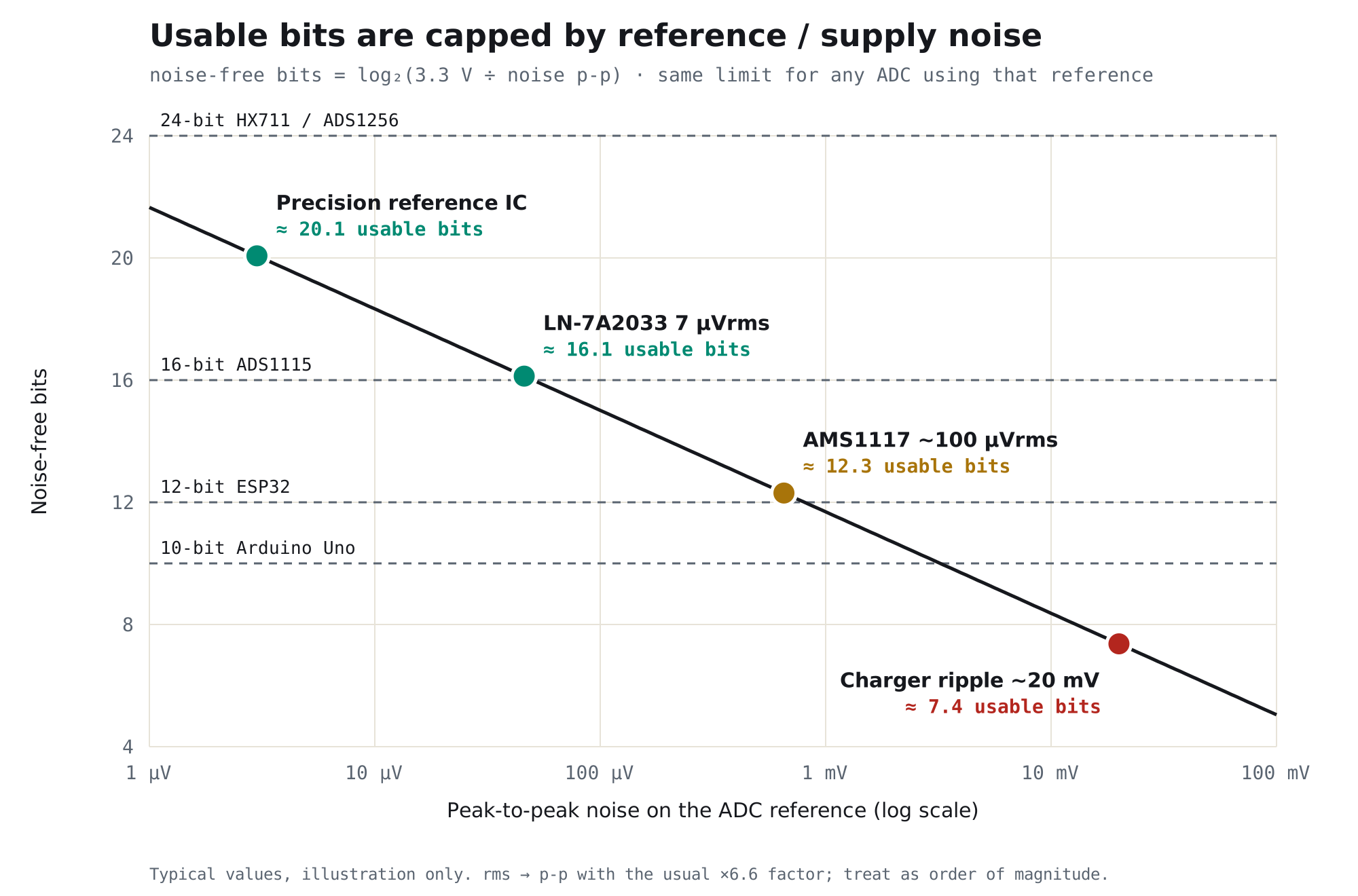
The number of bits you can actually trust is set by the ratio of the reference voltage to the noise on it: usable bits ≈ log₂(Vref ÷ noise p-p). That limit is the same whatever ADC you plug in.
Why supply noise goes straight into the reading
Path 1: the supply is the reference
On an Arduino Uno the default reference is AVCC, the board’s 5 V. On HX711 load-cell boards the bridge excitation and the reference come from the same analog supply. Many sensor modules output a fraction of their own supply. In all these cases, a 1% wobble on the supply is a 1% wobble in the result. For bridge and divider sensors the wobble partly cancels, but only if the sensor and the reference share exactly the same node.
Path 2: limited PSRR, and it falls with frequency
ADCs with an internal reference (ADS1115, ESP32) are better, but not immune. Their power-supply rejection ratio (PSRR) is strong for slow mains ripple and much weaker at the hundreds of kilohertz where phone chargers and buck converters switch.
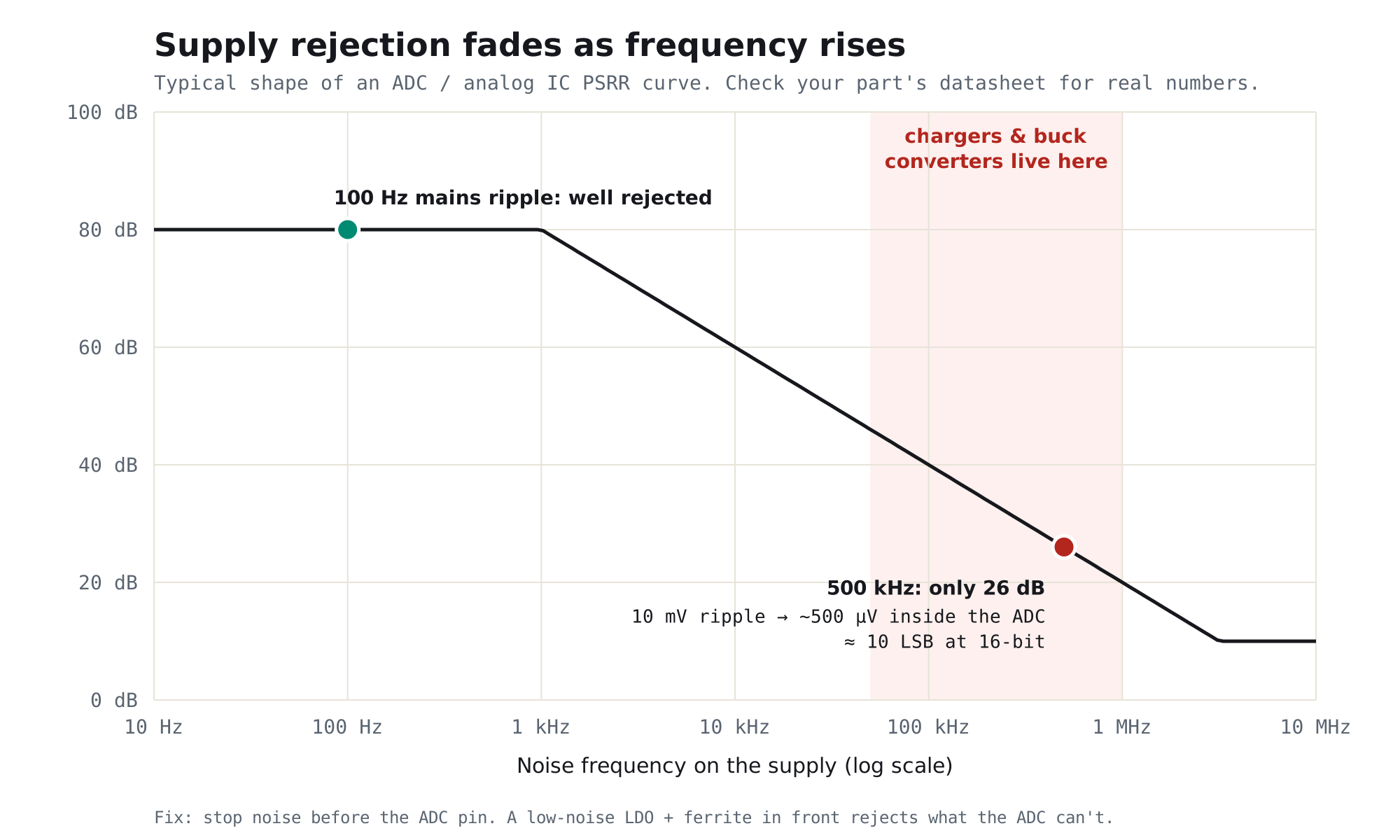
So noise has to be stopped before it reaches the ADC’s supply pin. That’s the job of a low-noise linear regulator with ferrite filtering: it rejects the switching noise the ADC itself can’t.
Measure your real usable bits in 2 minutes
Don’t trust the number on the box. Put a perfectly steady voltage on the input, a single AA cell (≈1.5 V, + to the analog pin, − to GND), read it a few hundred times and see how many counts it jumps:
// Real usable bits = log2(full scale / peak-to-peak counts)
const long FULL_SCALE = 1024;     // Uno 10-bit: 1024 · ESP32: 4096 · ADS1115 (+ only): 32768

void setup() { Serial.begin(115200); }

void loop() {
  long lo = 2147483647L, hi = -2147483647L;
  for (int i = 0; i < 256; i++) {
    long v = analogRead(A0);       // replace with your ADC's read function
    if (v < lo) lo = v;
    if (v > hi) hi = v;
    delay(2);
  }
  long pp = hi - lo + 1;           // +1: a perfectly steady reading still spans one code
  Serial.print("p-p counts: "); Serial.print(pp);
  Serial.print("   usable bits: "); Serial.println(log(FULL_SCALE / (double)pp) / log(2.0), 1);
  delay(1000);
}
Run it twice: once with the board on a phone charger, once with the analog side on a clean supply. The difference is what your supply is costing you.
Fix these before you buy more bits
- A low-noise analog supplyPower the ADC and sensors from a dedicated low-noise linear regulator, after any switching converter, with ferrite filtering. Never share it with Wi-Fi, motors or LEDs.
- A clean referenceIf the ADC uses its supply as the reference, the supply is your accuracy. For about 16 usable bits a low-noise LDO is enough; for 20+ bits use a dedicated precision reference IC.
- Grounding and layoutKeep digital and load currents out of the analog ground. Join grounds at one point, keep analog wires short and away from switching parts.
- Source impedanceHigh-impedance sensors can’t charge the ADC’s sampling capacitor in time. Add a 100 nF capacitor at the pin or a buffer amplifier.
- Filtering and data rateAn RC filter at the input stops noise above your signal’s bandwidth. On sigma-delta ADCs (HX711, ADS1115, ADS1256), a lower data rate gives more usable bits. Averaging helps random noise only.
- Calibration and driftCalibrate offset and gain against known inputs, and let things warm up. Resolution doesn’t fix a wrong reading, only a coarse one.
Which ADC for which job?
| Need | Sensible choice | What it needs to deliver |
|---|---|---|
| Pots, switches, rough levels | Arduino 10-bit | A reasonably quiet supply |
| General sensors with Wi-Fi | ESP32 12-bit | ADC1 pins, 100 nF, averaging; expect fewer than 12 usable bits |
| Accurate voltages, pH, thermistors | ADS1115 16-bit | A low-noise 3.3 V supply for the ADC and sensor |
| Load cells, strain gauges | HX711 / ADS1232 24-bit | Ratiometric bridge, clean analog supply, low data rate |
| Lab-grade measurement | ADS1256 / ADS1220 24-bit | Precision reference IC, careful layout, clean analog supply |
The analog supply we designed for this
TrueVolt LN-7A2033 · Ultra-low-noise 3.3 V module
A quiet 3.3 V for your ADC, its reference and your sensors.
- 7 µVrms noise: supports about 16 usable bits on a 3.3 V reference
- 95 dB ripple rejection at 1 kHz, plus ferrite filtering for switching noise
- 300 mA: an ADS1115 or HX711 plus several sensors
- Genuine TI TPS7A2033, Samsung capacitors, aluminium PCB
- For 20+ bit work: use it as the clean analog supply alongside a precision reference
For engineers: resolution, ENOB and noise-free bits
1. Three numbers that are often confused
| Term | Definition | What it tells you |
|---|---|---|
| Resolution | N bits: the number of output codes, 2N | The size of one step. Says nothing about noise or error |
| ENOB | (SINAD − 1.76 dB) ÷ 6.02 | Effective bits for AC signals, including noise and distortion |
| Effective resolution | log₂(full scale ÷ rms noise) | Common on sigma-delta datasheets |
| Noise-free bits | log₂(full scale ÷ peak-to-peak noise), with p-p ≈ 6.6 × rms | Bits that don’t flicker. About 2.7 bits below effective resolution |
For DC measurements (sensors, scales, voltages), noise-free bits is the most honest number, and it’s what the test above measures.
2. Supply and reference noise, worked through
With a ratiometric reference, a fractional error on the reference is the same fractional error on the result. Noise-free bits from the reference alone are log₂(Vref ÷ Vnoise,p-p):
| Reference on a 3.3 V rail | Noise (p-p) | Noise-free bits, max |
|---|---|---|
| Rail with charger ripple | ≈ 20 mV | ≈ 7.4 |
| Shared rail with Wi-Fi bursts | ≈ 10 mV | ≈ 8.4 |
| AMS1117 (≈100 µVrms) | ≈ 0.65 mV | ≈ 12.3 |
| TPS7A2033 (7 µVrms, 10 Hz–100 kHz) | ≈ 46 µV | ≈ 16.1 |
| Precision reference IC | a few µV | ≈ 20 |
The ADC’s own noise and the input noise add on top (root-sum-square), so the real result is always a bit lower. For internal-reference ADCs, divide the supply noise by the ADC’s PSRR at that frequency before comparing: 10 mV at 500 kHz with 26 dB of rejection is still about 500 µV, or ten 16-bit steps.
3. What averaging can and can’t do
Averaging N samples reduces random noise by √N: four times the samples gains one bit. It does nothing for slow drift, offset, gain error or non-linearity. Mains hum averages out only if the window covers whole mains cycles. Averaging rescues a few bits; it can’t replace a quiet supply.
Frequently asked questions
Does a higher-resolution ADC give higher accuracy?
Not by itself. Resolution sets the step size; accuracy depends on noise, the reference, offset, gain and linearity errors. If the supply or reference is noisy, extra bits only measure that noise. A 24-bit ADC with 10 mV of noise on a 3.3 V reference delivers about 8 usable bits.
What is the difference between ADC resolution and accuracy?
Resolution is how finely the ADC divides its input range (for example 216 steps). Accuracy is how close the reading is to the true value, including noise, reference error, offset, gain error and non-linearity. A coarse ADC can be accurate, and a fine one can be wildly wrong.
What are noise-free bits and ENOB?
Noise-free bits are the bits that don’t flicker: log₂ of full scale divided by peak-to-peak noise. ENOB (effective number of bits) is calculated from the ADC’s signal-to-noise-and-distortion ratio: (SINAD − 1.76 dB) ÷ 6.02. Both are usually several bits lower than the nominal resolution.
Why is my 24-bit ADC reading so noisy?
At 24 bits on a 3.3 V reference, one step is about 0.2 µV, so almost any supply or reference noise spans thousands of steps. Use a low-noise analog supply, a clean or precision reference, a ratiometric connection for bridge sensors, and a low data rate.
Why does the ESP32’s 12-bit ADC look worse than an Arduino’s 10-bit?
Smaller steps show more of the noise, and the ESP32’s ADC has noticeable noise and non-linearity of its own, plus Wi-Fi bursts on the same supply. Its usable bits are often fewer than 12. Use ADC1 pins, a 100 nF capacitor, averaging and a clean sensor supply, or an external ADC.
How does power-supply noise affect ADC readings?
Two ways. When the supply is the reference (Arduino AVCC, many sensor modules), its noise scales the reading directly. When the ADC has an internal reference, supply noise still leaks in through limited PSRR, which gets worse at higher frequencies where chargers and switching regulators operate.
What power supply do I need for a 16-bit or 24-bit ADC?
A dedicated low-noise linear regulator for the analog side, placed after any switching converter. For example, the Ramanu TrueVolt LN-7A2033 (TI TPS7A2033, 7 µVrms, 95 dB PSRR at 1 kHz) supports about 16 noise-free bits on a 3.3 V reference. For 20+ bits, pair a clean analog supply with a precision voltage-reference IC.
Fix it today
Get the bits you already paid for
One small module between your 5 V and your ADC: quiet 3.3 V, genuine TI, made in India.