Datasheet explained · Texas Instruments · Load switch
TPS22919 Datasheet Explained: Specs, Pinout & Application Circuit
The TPS22919 datasheet describes a tiny switch that turns a power rail on gently instead of slamming it on. Here’s what each pin does, how to calculate inrush, and when it beats a bare MOSFET.
Ramanu Systems · Pune, India · Based on TI datasheet SLVSEN5B
The TPS22919 is a 1.5 A load switch from Texas Instruments: a low-resistance MOSFET with its driver, soft-start and output discharge built in, in a 6-pin SC-70. A microcontroller pin turns a 1.6 to 5.5 V rail on and off through it, and the controlled turn-on keeps inrush current from browning out the rest of the board.
Is the TPS22919 right for your design?
It’s a good fit if:
- Turning on a module or sensor resets your ESP32 or Arduino
- You want to cut a peripheral’s power completely during sleep
- The load has big capacitors that would otherwise draw a surge
- You need the rail to drop to 0 V quickly when switched off
- Your rail is 1.8, 3.3 or 5 V and under 1.5 A
- You want one part instead of a MOSFET, driver and resistors
Look elsewhere if:
- Your rail is above 5.5 V (12 V, 24 V)
- You need more than 1.5 A continuous
- You need to tune the rise time (it’s fixed)
- The output can be driven above the input while off
TPS22919 key specifications
| Parameter | Value | Condition / note |
|---|---|---|
| Input voltage | 1.6 to 5.5 V | 6 V absolute maximum |
| Continuous current | 1.5 A | 2.5 A pulsed (2 ms, 2% duty) |
| On-resistance | 89 mΩ at 5 V | 90 mΩ at 3.6 V, 105 mΩ at 1.8 V (typ, 25 °C) |
| Quiescent current | 8 µA | Switch on, 3.6 V |
| Shutdown current | 2 nA | Switch off, 3.6 V, 25 °C (20 nA max) |
| ON thresholds | On above 1 V, off below 0.35 V | Works with 1.8, 3.3 and 5 V logic |
| Turn-on slew rate | 3.2 mV/µs at 5 V | 2.7 mV/µs at 3.6 V, 1.8 mV/µs at 1.8 V. Fixed. |
| Rise time | 1.28 ms at 5 V | 0.1 µF load, 100 Ω |
| Quick output discharge | 24 Ω internal | Through the QOD pin |
| Short-circuit current | 3 A typ | Responds in about 2 µs |
| Thermal shutdown | 180 °C | Restarts at 145 °C |
TPS22919 pinout
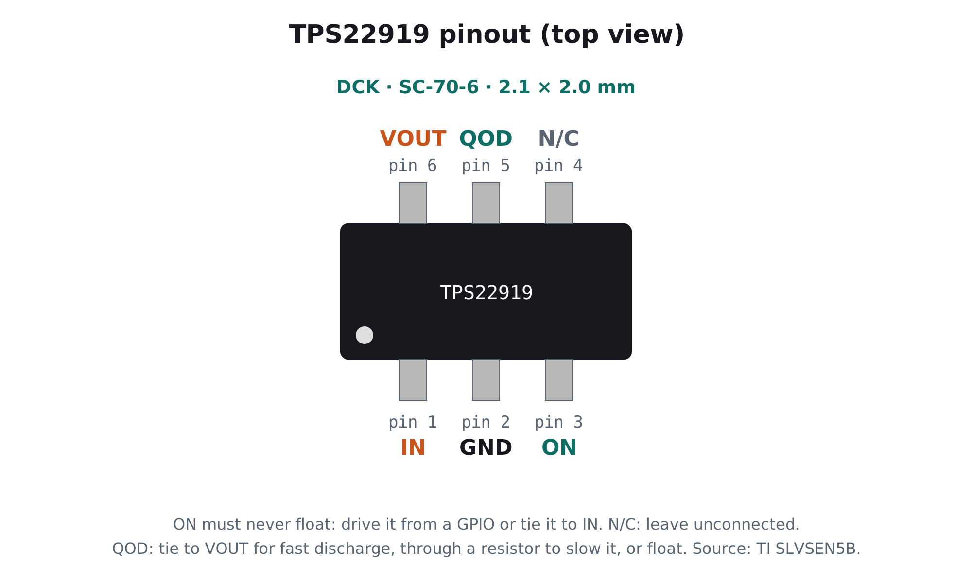
| Pin | Name | What it does |
|---|---|---|
| 1 | IN | Switch input: the rail you want to switch |
| 2 | GND | Ground |
| 3 | ON | Active-high control. TI says don’t leave it floating: drive it from a GPIO or tie it to IN. |
| 4 | N/C | No connection; leave it open |
| 5 | QOD | Quick output discharge: connect to VOUT directly, through a resistor, or leave open |
| 6 | VOUT | Switched output to your load |
TPS22919 typical application circuit
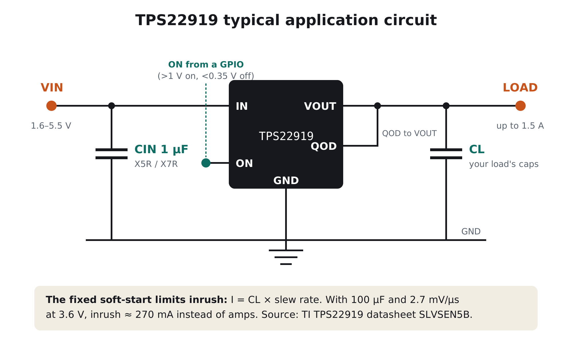
- 1 µF on the inputIt stops the input rail dipping when the switch turns on. If your supply is slow to respond (long wires, a weak regulator), add more bulk capacitance on IN.
- Drive ON from a GPIOAbove 1 V turns it on, below 0.35 V turns it off, so a 1.8 V or 3.3 V MCU pin drives it directly. For an always-on rail with soft-start, tie ON to IN.
- Decide what QOD doesTie QOD to VOUT and the output is pulled to 0 V through about 24 Ω when you switch off. Add a resistor in series to slow that discharge, or leave QOD open to let the load discharge on its own.
How to calculate inrush current
When a switch connects a rail to a discharged capacitor, the current is I = C × dV/dt. A bare MOSFET switches in microseconds, so even a modest capacitor pulls amps for a moment and drags the supply down; that’s the classic “ESP32 resets when I turn on the sensor”. The TPS22919 fixes dV/dt at its slew rate, so TI’s formula is simply I_inrush = CL × slew rate (mA = µF × mV/µs):
| Load capacitance | Inrush at 3.3–3.6 V (2.7 mV/µs) | Inrush at 5 V (3.2 mV/µs) |
|---|---|---|
| 10 µF | ≈27 mA | ≈32 mA |
| 47 µF | ≈127 mA | ≈150 mA |
| 100 µF | ≈270 mA | ≈320 mA |
| 470 µF | ≈1.27 A | ≈1.5 A (at the limit) |
Your load’s own current adds on top. Our inrush current application note works through a full example, including why a fuse that passes every bench test can still blow in the field.
And the fall time when you switch off
With QOD connected, TI gives t_FALL = 2.2 × (R_DIS ∥ R_L) × C_L, where R_DIS is the internal 24 Ω plus any resistor you add. Example: 100 µF with QOD tied straight to VOUT and a light load falls in about 2.2 × 24 Ω × 100 µF ≈ 5 ms.
Skip the SC-70 soldering
PureSwitch-22919: the TPS22919 on a ready module
Switch a sensor, relay or module from a GPIO without browning out your ESP32 or Arduino.
- Genuine TI TPS22919: 1.5 A, about 90 mΩ
- Controlled soft-start and quick output discharge
- Schottky flyback diode for switching relay coils
- Designed & made in Pune, India
TPS22919 vs a bare P-channel MOSFET
| TPS22919 | P-MOSFET + resistor | |
|---|---|---|
| Inrush control | Built in, fixed slew rate | Needs an extra RC network on the gate |
| Logic drive | Any 1.8–5 V GPIO, directly | Often needs an NPN or N-MOSFET to pull the gate fully |
| Output discharge | 24 Ω QOD built in | Extra resistor, always drawing current |
| Short-circuit response | Limits current in about 2 µs | None |
| Voltage and current | 5.5 V, 1.5 A | Whatever the MOSFET is rated for |
For engineers: the finer print
1. Voltage drop and heat at full current
At 1.5 A and 89 mΩ, the switch drops about 134 mV and dissipates about 0.2 W. With TI’s 210.7 °C/W for the SC-70, that’s roughly a 42 °C rise: comfortable, but give the pins some copper. At 1.8 V input the resistance rises to 105 mΩ typical (300 mΩ max), so check the drop on low-voltage rails.
2. The slew rate depends on VIN
The ramp is fixed by the chip, but it scales with input voltage: 1.8 mV/µs at 1.8 V, 2.7 mV/µs at 3.6 V, 3.2 mV/µs at 5 V. Use the value for your rail in the inrush formula. Turn-on delay plus rise is around 1.5 to 2 ms, so give the load that long before you talk to it.
3. ON pin behaviour
ON has a weak pulldown of about 530 kΩ when it’s low, but TI’s pin table still says not to leave it floating. Drive it from a push-pull GPIO; if the MCU can be unpowered while VIN is present, add your own pulldown so the switch stays off during MCU reset.
Frequently asked questions
What is the TPS22919?
The TPS22919 is a 1.5 A, 5.5 V single-channel load switch from Texas Instruments with about 89 mΩ on-resistance, a fixed soft-start slew rate, quick output discharge and short-circuit current limiting, in a 6-pin SC-70 package.
What is the TPS22919 pinout?
Pin 1 IN, pin 2 GND, pin 3 ON, pin 4 no connection, pin 5 QOD (quick output discharge), pin 6 VOUT, in the SC-70-6 (DCK) package.
What does the QOD pin do on the TPS22919?
QOD connects an internal 24 Ω discharge path. Tie it to VOUT to pull the output to 0 V quickly when the switch turns off, add a series resistor to slow the discharge, or leave it open to disable it.
How do I calculate TPS22919 inrush current?
Multiply the load capacitance by the slew rate: I (mA) = C (µF) × slew rate (mV/µs). At 3.6 V the slew rate is about 2.7 mV/µs, so 100 µF of load capacitance draws about 270 mA during turn-on, plus the load’s own current.
Can I leave the TPS22919 ON pin floating?
No. Although ON has a weak internal pulldown, TI’s pin description says not to leave it floating. Drive it from a GPIO or tie it to IN for always-on operation.
Why does my ESP32 reset when I switch on a sensor?
Usually inrush: switching a discharged capacitor onto the 3.3 V rail pulls a brief surge that drops the rail below the ESP32’s brown-out threshold. A load switch with a controlled slew rate, such as the TPS22919, limits that surge to a few hundred milliamps.
Build with it today
Switch power without the brown-out
The genuine TPS22919 on a breadboard-friendly module. Made in India.