Datasheet explained · Texas Instruments · Nanopower LDO · TPS7A0333
TPS7A03 Datasheet Explained: Specs, Pinout & Application Circuit
The TPS7A03 datasheet’s headline is 200 nA. Here is what that buys you in battery life, what it costs in noise and transient response, and everything else you need to design it in.
Ramanu Systems · Pune, India · Based on TI datasheet SBVS375D
The TPS7A03 is a 200 mA nanopower LDO from Texas Instruments that idles at just 200 nA. It takes 1.5 to 6.0 V in and gives a fixed 0.8 to 5.0 V out; the 3.3 V version is the TPS7A0333. It’s built for products that sleep most of the time: sensor nodes, wearables, coin-cell and energy-harvesting designs.
Is the TPS7A03 right for your design?
It’s a good fit if:
- Your product sleeps for seconds to hours between short bursts
- You run from a coin cell, AA cells, Li-ion or a harvester
- Your bursts stay under 200 mA (BLE, LoRa, sensor reads)
- You want the regulator to stay frugal even as the cell runs low
- You need an EN pin that stays off if left floating
- Board space is tight
Look elsewhere if:
- You power an ESP32 with Wi-Fi on (its bursts exceed 200 mA)
- The rail feeds audio, RF front-ends or a precision ADC
- You need more than 22 µF of output capacitance
- Your load is always on (idle current stops mattering)
TPS7A03 key specifications
| Parameter | Value | Condition / note |
|---|---|---|
| Input voltage | 1.5 to 6.0 V | 6.5 V absolute maximum |
| Output voltage | 0.8 to 5.0 V, fixed | 3.3 V = TPS7A0333 |
| Output current | 200 mA | Recommended maximum |
| Quiescent current | 200 nA | No load, 25 °C (250 nA max; 300 nA max to 85 °C) |
| Quiescent current in dropout | 220 nA | Stays low as the battery falls below the output |
| Shutdown current | 3 nA (10 nA max) | EN low, 25 °C |
| Dropout voltage | 270 mV max | 200 mA, 3.3 to 5.0 V outputs, up to 85 °C (310 mV to 125 °C) |
| Output accuracy | ±1% (±1.5% over temperature) | Outputs 1.5 V and above |
| PSRR | 55 dB at 1 kHz | 30 mA load |
| Output noise | 130 µVrms | 10 Hz–100 kHz at 0.8 V out; rises with output voltage |
| Current limit | 450 mA typ (240 mA min) | Folds back to about 65 mA into a short |
| Capacitors | 1 µF in, 1 to 22 µF out (effective) | 0.5 µF effective is the absolute minimum |
| Thermal shutdown | 170 °C | Restarts at 145 °C |
TPS7A03 pinout
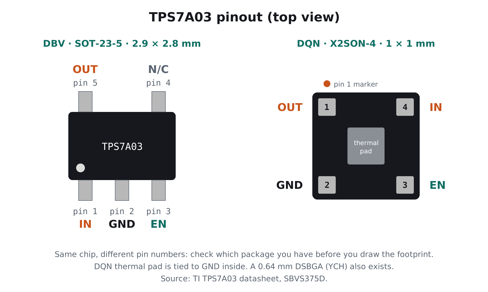
| Pin | SOT-23-5 (DBV) | X2SON-4 (DQN) | DSBGA-4 (YCH) | Function |
|---|---|---|---|---|
| IN | 1 | 4 | A1 | Input supply |
| GND | 2 | 2 | B2 | Ground |
| EN | 3 | 3 | B1 | Enable. Above 1.1 V = on, below 0.3 V = off. Floating = off. |
| OUT | 5 | 1 | A2 | Regulated output |
| N/C | 4 | – | – | No internal connection |
| Thermal pad | – | pad | – | Tied to ground internally |
TPS7A03 typical application circuit
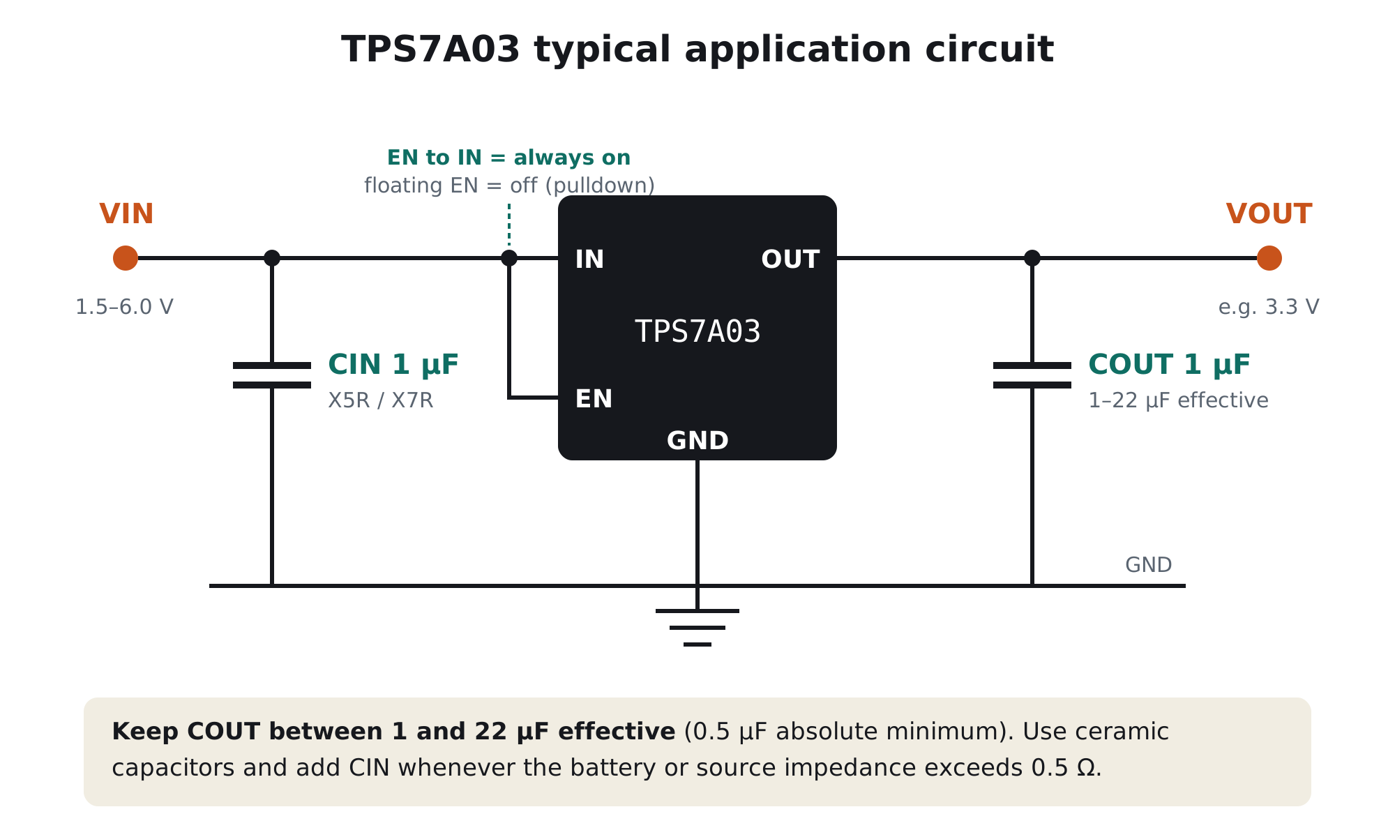
- Output capacitor: 1 to 22 µF, no moreThis is the TPS7A03’s unusual rule. Below 0.5 µF effective it can oscillate, and TI’s recommended range ends at 22 µF effective. Don’t hang a 100 µF bulk capacitor directly on its output.
- Input capacitor when the source is weakAdd 1 µF on IN, and keep it whenever the source impedance is above about 0.5 Ω: coin cells and long battery leads qualify.
- EN: tie it or drive itTie EN to IN for always-on, or drive it from a GPIO. Thanks to a smart pulldown, a floating EN keeps the regulator off rather than half-on.
What 200 nA means for battery life
For a product that sleeps most of the time, the regulator’s idle current is often the biggest drain. Here’s how long the regulator alone would take to empty a typical 225 mAh CR2032 coin cell (ignoring the rest of the circuit):
| Regulator | Idle current | Time to drain 225 mAh on idle current alone |
|---|---|---|
| AMS1117 | ≈5 mA | ≈2 days |
| TLV740P | 50 µA | ≈6 months |
| TPS7A03 | 200 nA | Decades: the cell’s own self-discharge becomes the limit |
The regulator stops being the problem. Your microcontroller’s sleep current, sensor leakage and pull-up resistors then decide battery life, so budget those next. Our quiescent current guide works through a full duty-cycle example.
Skip the SMD soldering
TrueVolt NP-7A0333: the TPS7A0333 on a ready module
Your regulator should not be the reason your battery dies.
- Genuine TI TPS7A0333: 200 nA idle, 220 nA as the cell runs low
- 200 mA for LoRa and BLE radio bursts, 0.27 V max dropout
- Reverse-current Schottky protection, aluminium PCB
- Designed & made in Pune, India
TPS7A03 alternatives
| Part | Choose it when |
|---|---|
| TPS7A20 | The rail must be quiet (7 µVrms) and 6.5 µA idle is acceptable. Ours: TrueVolt LN-7A2033 |
| TLV740P | Always-on MCU power up to 300 mA where idle current doesn’t matter. Ours: TrueVolt74033 |
| Buck converter | Large, frequent bursts (ESP32 Wi-Fi) from a high-voltage battery, where efficiency under load beats idle current |
For engineers: what nano-amp idle costs
1. Noise is hundreds of microvolts
With so little bias current, the internal reference and error amplifier are noisy: 130 µVrms at 0.8 V out, and TI’s curves show several hundred µVrms at higher outputs (about 270 µVrms at 1.8 V and 710 µVrms at 5.0 V, 1 mA load). That’s harmless for logic and most sensors, but too much for audio or a high-resolution ADC reference.
2. Load steps need help from COUT
TI quotes under 10 µs settling and about 80 mV undershoot for a 1 to 50 mA step. A radio waking from sleep is exactly that kind of step. Use the top of the allowed output range (around 10 to 22 µF effective) for radio loads, and check that 80 mV of dip is inside your MCU’s brown-out margin.
3. Ground current tracks load
Under load, ground current is a small percentage of output current (about 1% between 20 µA and 1 mA, falling to 0.15% above 100 mA), so efficiency stays close to the ideal VOUT ÷ VIN at every load.
Frequently asked questions
What is the TPS7A03?
The TPS7A03 is a 200 mA nanopower LDO linear regulator from Texas Instruments with 200 nA typical quiescent current, 1.5 to 6.0 V input, fixed 0.8 to 5.0 V output and 270 mV maximum dropout at 200 mA. The 3.3 V version is the TPS7A0333.
What is the TPS7A03 pinout?
In SOT-23-5: pin 1 IN, pin 2 GND, pin 3 EN, pin 4 no connection, pin 5 OUT. In X2SON-4: pin 1 OUT, pin 2 GND, pin 3 EN, pin 4 IN with a thermal pad tied to ground. In the DSBGA: A1 IN, A2 OUT, B1 EN, B2 GND.
What output capacitor does the TPS7A03 need?
Between 1 and 22 µF of effective ceramic capacitance after DC-bias derating, with 0.5 µF as the absolute minimum for stability. Larger output capacitors are outside TI’s recommended range.
Can the TPS7A03 power an ESP32?
Not with Wi-Fi active. The TPS7A03 is rated for 200 mA, while Espressif recommends a supply that can deliver at least 500 mA for the ESP32. It suits BLE, LoRa and low-power MCUs whose bursts stay below 200 mA.
How long will a coin cell last with a TPS7A03?
The regulator’s own 200 nA would take decades to drain a 225 mAh CR2032, longer than the cell’s shelf life. Battery life is then set by your microcontroller’s sleep current, sensor leakage and how often the radio transmits.
Can I leave the TPS7A03 EN pin floating?
Yes, but the output will be off. EN has a smart pulldown of about 500 kΩ that holds the regulator off when EN floats. Tie EN to IN or drive it above 1.1 V to turn it on.
Build with it today
Years on battery, not weeks
The genuine TPS7A0333, on a module you can wire in minutes. Made in India.